
Home
>> Products
>> MITSUBISHI
>> Ans/QnAs series PLC
>> CPU power module
>> A1S61PN | MITSUBISHI Power module A1S61PN
A1S61PN | MITSUBISHI Power module A1S61PN
MITSUBISHI A1S61PN Manual And Instructions
A1S61PN datasheetPDF datasheet
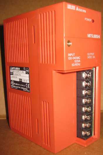
MITSUBISHI A1S61PN Product information and technical parameters:
Brand: MITSUBISHI
Name: Power module
Model: A1S61PN
Input voltage: AC100-240V.
Rated output: DC5V, 5A.
The power supply module is connected with the external power supply,
AnS programmable controller to provide the required DC5V,
They are inserted in the slot of the special power supply component on the base board,
The output of the DC5V is powered by the power supply on the substrate to the component.
The input voltage of the component is related to the selected model.
A1S61PN/62PN has Deng generation A1S61P/A1S62P, A1S61PEU/A1S62PEU.
...More relevant models >>>>
A1S61PN datasheetPDF datasheet
MITSUBISHI A1S61PN Product information and technical parameters:
Brand: MITSUBISHI
Name: Power module
Model: A1S61PN
Input voltage: AC100-240V.
Rated output: DC5V, 5A.
The power supply module is connected with the external power supply,
AnS programmable controller to provide the required DC5V,
They are inserted in the slot of the special power supply component on the base board,
The output of the DC5V is powered by the power supply on the substrate to the component.
The input voltage of the component is related to the selected model.
A1S61PN/62PN has Deng generation A1S61P/A1S62P, A1S61PEU/A1S62PEU.
SRAM+E2PROM memory card.
RAM capacity: 512KB.
E2PROM capacity: 512KB. Input and output points: 512 points.
Input / output data points: 8192 points.
Program capacity: 14K.
Basic command processing speed (LD command) s:0.2.
Internal storage RAM memory capacity: 64K
PLC in the program execution stage: according to the order of the user program order to store the order of each instruction,
After the corresponding operation and processing, the result is written to the output status register,
The contents of the output status register are changed with the execution of the program MITSUBISHI A1S61PN A1S61PN
Output refresh phase: when all instructions are executed,
The output status register is sent to the output latch in the output refresh stage,
And through a certain way (relay, transistor or transistor) output, drive the corresponding output equipment MITSUBISHI A1S61PN. . Type of input: DC source.
Input points: 16 points.
Input voltage: DC24.
Input current: 7mA.
Connection mode: terminal row.
Common common point: 16.
Functional block diagram language is a kind of PLC programming language, which is similar to digital logic circuit MITSUBISHI A1S61PN.
The function module is used to represent the function of the module,
Different function modules have different functions.
Functional module figure programming language features: functional block diagram programming language is characterized by a functional module for the unit,
Analysis and understanding of the control scheme is simple and easy: function module is to use graphical form of expression,
Intuitive, for a digital logic circuit based on the design of the staff is very easy to master the programming;
Control system with complex scale and complex control logic,
Because the function module diagram can clearly express the function relation, the programming debugging time is greatly reduced. Output type: transistor source.
Output points: 16 points.
Load voltage: DC12/24.
Load current: 0.8A.
Connection mode: terminal row.
Common public end points: 8.
Switching value, also known as logic, refers to only two values, 0 or 1, ON or OFF.
It is the most common control, it is the advantage of PLC control,
Is also the most basic application of PLC.
Switch volume control is designed to,
According to the current inputt combination of the switch quantity and the history of the input sequence,
So that PLC generates the corresponding switching output,
In order to make the system work in a certain order A1S61PN.
So, sometimes also known as the order control.
And seqquential control is divided into manual, semi-automatic or automatic A1S61PN.
And the control principle is decentralized, centralized and hybrid control three.
...More relevant models >>>>
 Last one:
  next one:
 Related download