
Home
>> Products
>> MITSUBISHI
>> A/QnA series PLC
>> CPU
>> A273UCPU | MITSUBISHI cpu module A273UCPU
A273UCPU | MITSUBISHI cpu module A273UCPU
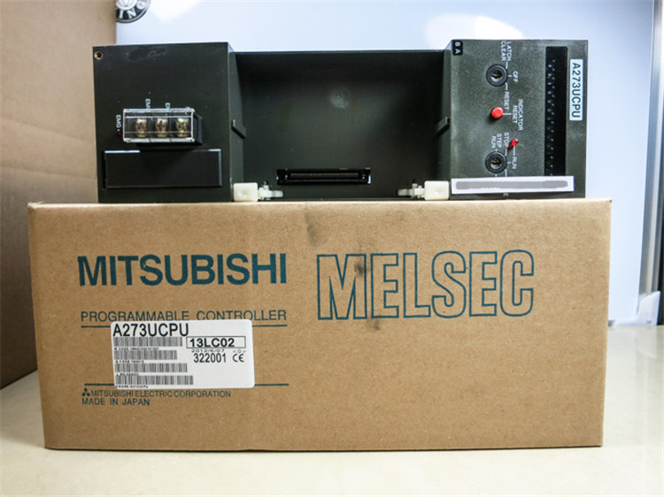
MITSUBISHI A273UCPU Manual And Instructions
A273UCPU Common InstructionsProgramming Manual
A273UCPU HardwareUser's Manual
A273UCPU AD57 control InstructionsProgramming Manual
A273UCPU Dedicated InstructionsProgramming Manual
A273UCPU FundamentalsProgramming Manual
A273UCPU PID Control InstructionsProgramming Manual
MITSUBISHI A273UCPU Product information and technical parameters:
Brand: MITSUBISHI
Name: cpu module
Model: A273UCPU
...More relevant models >>>>
A273UCPU Common InstructionsProgramming Manual
A273UCPU HardwareUser's Manual
A273UCPU AD57 control InstructionsProgramming Manual
A273UCPU Dedicated InstructionsProgramming Manual
A273UCPU FundamentalsProgramming Manual
A273UCPU PID Control InstructionsProgramming Manual
MITSUBISHI A273UCPU Product information and technical parameters:
Brand: MITSUBISHI
Name: cpu module
Model: A273UCPU
8 channels.
4 wire platinum measuring antibodies (Pt100, JPt100).
Transform speed: 40ms/1 channel.
38 point terminal station.
When the switch is off, the diode does not emit light, and the transistor is not on the way. Internal circuit input signal.
It is through the input interface circuit to the external switch signal into PLC internal can accept the digital signal MITSUBISHI A273UCPU.
MITSUBISHI PLC is the main product in the production of MITSUBISHI motor in Dalian A273UCPU
It uses a kind of programmable memory for its internal storage procedures,
Execute logic operation, sequence control, timing, counting and arithmetic operations, user oriented instruction,
And through digital or analog input / output control of various types of machinery or production process MITSUBISHI A273UCPU.
Input status and input information input from the input interface,
CPU will be stored in the working data memory or in the input image register.
And then combine the data and the program with CPU.
The result is stored in the output image register or the working data memory,
And then output to the output interface, control the external drive.
PLC selection with the development of PLC technology, more and more types of PLC products,
Function is becoming more and more perfect, and its application is more and more extensive MITSUBISHI A273UCPU.
Different series of different models of PLC has different performance, applicable occasions also have different emphasis,
Price also has a greater difference. Therefore PLC selection,
Under the premise of meeting the control requirements,
Should consider the best performance to price ratio, a reasonable choice of PLC.
The working process of the input interface circuit: when the switch is closed, the diode light,
The transistor is then guided to the internal circuit and input signal under the irradiation of the light. Input points: 16 points.
Input voltage and current: 240V ~ 10mA AC100.
Input response time: 35ms.
16 point /1 a public side.
Output points: 12 points.
Output voltage: AC100 ~ 240V.
OFF leakage current: 3mA.
Output response time: 0.5Hz+1ms.
Output type: bidirectional thyristor output.
8 point /1 a public end, 4 points / a public end.
36 point terminal station.
With short circuit protection.
With the surge absorber.
Control solenoid valve required I/O points by the action principle of the solenoid valve can be known,
A single coil solenoid valve with PLC control to 2 input and 1 output,
A double coil solenoid valve requires 3 inputs and 2 outputs,
A button needs an input; a light sensitive switch needs 4 or 2 inputs,
A signal lamp needs 1 output, band switch,
Several bands are required for several inputs,
In general, a variety of position switches are required to take up 2 input points.
MITSUBISHI PLC is the main product in the production of MITSUBISHI motor in Dalian.
It uses a kind of programmable memory for its internal storage procedures,
Execute logic operation, sequence control, timing, counting and arithmetic operations, user oriented instruction,
And through digital or analog input / output control of various types of machinery or production process.
The number of I/O thyristor DC motor control required tube DC motor speed control system is the main form of DC speed regulation,
The thyristor rectifier unit is used to supply power to the DC motor.
PLC control of the DC drive system, the input of the PLC in addition to the main signal outside the signal,
We need to consider the switching signal, the fault signal transmmission device, brake signal and fan fault signal A273UCPU.
The output of the PLC mainly consider the speed command signal positive 1~3 level, 1~3 level, allowing reverse switching signal and brake open signal etc..
In general, a reversible DC drivee system controlled by PLC is approximately 12 input points and 8 output points,
An irreversible DC drive system requires 9 inputs and 6 output points A273UCPU.
...More relevant models >>>>
 Last one:
  next one:
 Related download