
Home
>> Products
>> MITSUBISHI
>> A/QnA series PLC
>> Analog input / output module
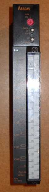
>> A68DAV | MITSUBISHI Analog output module A68DAV
A68DAV | MITSUBISHI Analog output module A68DAV
MITSUBISHI A68DAV Manual And Instructions
A68DAV datasheetPDF datasheet
A68DAV User's Manual
MITSUBISHI A68DAV Product information and technical parameters:
Brand: MITSUBISHI
Name: Analog output module
Model: A68DAV
8 channels.
Input: DC-10 ~ 10V.
Output (resolution): -4000 ~ 4000/-8000 ~ 8000/-12000 ~ 12000.
Transform speed: 40ms/8 channel.
38 point terminal station.
Input status and input information input from the input interface,
CPU will be stored in the working data memory or in the input image register.
And then combine the data and the program with CPU.
The result is stored in the output image register or the working data memory,
And then output to the output interface, control the external drive.
PLC selection with the development of PLC technology, more and more types of PLC products,
Function is becoming more and more perfect, and its application is more and more extensive.
Different series of different models of PLC has different performance, applicable occasions also have different emphasis,
Price also has a greater difference. Therefore PLC selection,
Under the premise of meeting the control requirements,
Should consider the best performance to price ratio, a reasonable choice of PLC.
The working process of the input interface circuit: when the switch is closed, the diode light,
The transistor is then guided to the internal circuit and input signal under the irradiation of the light.
When the switch is off, the diode does not emit light, and the transistor is not on the way. Internal circuit input signal.
It is through the input interface circuit to the external switch signal into PLC internal can accept the digital signal.
MITSUBISHI PLC is the main product in the production of MITSUBISHI motor in Dalian.
It uses a kind of programmable memory for its internal storage procedures,
Execute logic operation, sequence control, timing, counting and arithmetic operations, user oriented instruction,
And through digital or analog input / output control of various types of machinery or production process.
...More relevant models >>>>
A68DAV datasheetPDF datasheet
A68DAV User's Manual
MITSUBISHI A68DAV Product information and technical parameters:
Brand: MITSUBISHI
Name: Analog output module
Model: A68DAV
8 channels.
Input: DC-10 ~ 10V.
Output (resolution): -4000 ~ 4000/-8000 ~ 8000/-12000 ~ 12000.
Transform speed: 40ms/8 channel.
38 point terminal station.
Input status and input information input from the input interface,
CPU will be stored in the working data memory or in the input image register.
And then combine the data and the program with CPU.
The result is stored in the output image register or the working data memory,
And then output to the output interface, control the external drive.
PLC selection with the development of PLC technology, more and more types of PLC products,
Function is becoming more and more perfect, and its application is more and more extensive.
Different series of different models of PLC has different performance, applicable occasions also have different emphasis,
Price also has a greater difference. Therefore PLC selection,
Under the premise of meeting the control requirements,
Should consider the best performance to price ratio, a reasonable choice of PLC.
The working process of the input interface circuit: when the switch is closed, the diode light,
The transistor is then guided to the internal circuit and input signal under the irradiation of the light.
When the switch is off, the diode does not emit light, and the transistor is not on the way. Internal circuit input signal.
It is through the input interface circuit to the external switch signal into PLC internal can accept the digital signal.
MITSUBISHI PLC is the main product in the production of MITSUBISHI motor in Dalian.
It uses a kind of programmable memory for its internal storage procedures,
Execute logic operation, sequence control, timing, counting and arithmetic operations, user oriented instruction,
And through digital or analog input / output control of various types of machinery or production process.
Master / local station.
QnACPU use.
According to the control requirements of the system, using the appropriate design method to design MITSUBISHI PLC program.
Procedures to meet the requirements of system control as the main line,
Write one by one to achieve the control function or the sub task of the program,
Gradually improve the functions specified by the system MITSUBISHI A68DAV.
MITSUBISHI PLC initialization procedure A68DAV After MITSUBISHI PLC on power, the general need to do some of the initial operation,
In order to start making necessary preparations, to avoid the wrong operation of the system.
The main contents of the initialization program are: to some data area, counter and so on,
Data needed to restore some of the data area,
Set or reset some relays,
For some initial state display, etc MITSUBISHI A68DAV. . "Input and output points: 256 points.
Input / output data points: 256 points.
Program capacity: 6k.
Basic command processing speed (LD command) s:1.0.
Internal storage RAM memory capacity: 16k.
User program storage capacity: it is a measure of how much the user application can store the number of indicators MITSUBISHI A68DAV.
Usually in words or K words as units. 16 bit binary number is a word,
Every 1024 words are 1K words. PLC to store instructions and data in words.
General logical operation instructions each account for 1 words. Timer / counter,
Shift instruction accounted for 2 words. Data operation instructions for 2~4.
Integral type: the PLC components are installed together or a few pieces of printed circuit board,
And together with the power supply installed in the casing to form a single overall called the host or the basic unit, small, ultra small PLC using this structure.
Modular: PLC is the basic components of a separate module.
Medium and large PLC used this way. Easy maintenance. 5 slots.
Can be installed in the power supply unit for A series units installed QnA/.
Relay output interface circuit of PLC
Working process: when the internal circuit output digital signal 1,
There is a current flowing through, the relay coil has a current, and then the normally open contact is closed,
Provide load current and voltage.
When the internal circuit outputs a digital signal 0, there is no current flowing through it,
The relay coil does not have a current, and the normally open contact is broken off,
A current or voltage that is disconnected from the load.
It is through the output interface circuit to the internal digital circuit into a signal to make the load action or not action.
I/O points is an important indicator of PLC.
Reasonable selection of I/O points can not only satisfy the control requirements of the system,
And the total investment of the system is the lowest.
The input and output points and types of PLC should be deterrmined according to the analog quantity and switch quantity of the controlled object,
Generally an input / output element to take up an input / output point A68DAV.
Taking into account the future adjustment and expansion,
In general should be estimaated on the total number of points plus the amount of spare 20%~30% A68DAV.
The following describes the centralized control system I/O points of the estimate.
...More relevant models >>>>
 Last one: MITSUBISHI Analog output module A68DAI-S1
 next one: MITSUBISHI Analog output module A64DAIC
Related download