
Home
>> Products
>> MITSUBISHI
>> A/QnA series PLC
>> Network / serial communication module
>> AJ71QC24-R2 | MITSUBISHI Serial communication module AJ71QC24-R2
AJ71QC24-R2 | MITSUBISHI Serial communication module AJ71QC24-R2
MITSUBISHI AJ71QC24-R2 Manual And Instructions
AJ71QC24-R2 datasheetPDF datasheet
AJ71QC24-R2 HardwareUser's Manual
AJ71QC24-R2 HardwareUser's Manual
AJ71QC24-R2 Modem Function Additional VersionUser's Manual
MITSUBISHI AJ71QC24-R2 Product information and technical parameters:
Brand: MITSUBISHI
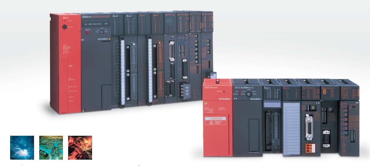
Name: Serial communication module
Model: AJ71QC24-R2
RS-232 2 channel.
Transfer speed: 0.3-19.2kbps.
Equipment layer / field bus CC-Link device layer is the PLC and other control devices and sensors and drive devices connected to the field network,
Network for the lowest layer of the whole network system.
Using CC-Link field bus connection, the number of wiring is greatly reduced,
Improve the maintainability of the system.
And, not just the amount of data ON/OFF and other switches,
Can also be connected to the ID system, bar code reader, inverter, man-machine interface and other intelligent devices,
From the completion of a variety of data communication, the management of the terminal production information can be realized,
On the centralized management of the state of the machine movement,
Make maintenance work efficiency also greatly improved.
Q series PLC in the use of CC-Link function better,
And easier to use.
...More relevant models >>>>
AJ71QC24-R2 datasheetPDF datasheet
AJ71QC24-R2 HardwareUser's Manual
AJ71QC24-R2 HardwareUser's Manual
AJ71QC24-R2 Modem Function Additional VersionUser's Manual
MITSUBISHI AJ71QC24-R2 Product information and technical parameters:
Brand: MITSUBISHI
Name: Serial communication module
Model: AJ71QC24-R2
RS-232 2 channel.
Transfer speed: 0.3-19.2kbps.
Equipment layer / field bus CC-Link device layer is the PLC and other control devices and sensors and drive devices connected to the field network,
Network for the lowest layer of the whole network system.
Using CC-Link field bus connection, the number of wiring is greatly reduced,
Improve the maintainability of the system.
And, not just the amount of data ON/OFF and other switches,
Can also be connected to the ID system, bar code reader, inverter, man-machine interface and other intelligent devices,
From the completion of a variety of data communication, the management of the terminal production information can be realized,
On the centralized management of the state of the machine movement,
Make maintenance work efficiency also greatly improved.
Q series PLC in the use of CC-Link function better,
And easier to use.
Input and output points: 2048 points.
Input / output data points: 8192 points.
Program capacity: 92k.
Basic command processing speed (LD command) S:0.15.
The length of time required to execute the instruction, the length of the user''s program, the type of instruction, and the speed of the CPU execution are very significant,
Generally, a scanning process, the fault diagnosis time,
Communication time, input sampling and output refresh time is less,
The execution time is accounted for the vast majority of MITSUBISHI AJ71QC24-R2 AJ71QC24-R2
The photoelectric coupler is composed of two luminous two extreme tubes and a photoelectric transistor.
Light emitting diode two: the input of a photo coupler and the change of electrical signal,
The light signal is generated by the light emitting diode, which is the same as the input signal MITSUBISHI AJ71QC24-R2.
The working process of the input interface circuit: when the switch is closed, the diode light,
The transistor is then guided to the internal circuit and input signal under the irradiation of the light.
When the switch is off, the diode does not emit light, and the transistor is not on the way MITSUBISHI AJ71QC24-R2. Internal circuit input signal.
It is through the input interface circuit to the external switch signal into PLC internal can accept the digital signal.
Photoelectric three levels: in the light of the light signal conduction, the degree of light signal and the intensity of the light signal.
The output signal has a linear relationship with the input signal in the linear operating region of the photoelectric coupler.
User program storage capacity: it is a measure of how much the user application can store the nuumber of indicators AJ71QC24-R2.
Usually in words or K words as units. 16 bit binary number is a word,
Every 1024 words are 1K words. PLC to store instructions and data in words.
General logical operation instructions each account for 1 words. Timerr / counter,
Shift instruction accounted for 2 words AJ71QC24-R2. Data operation instructions for 2~4.
MELSECNET/10, MELSECNET/H coaxial, input voltage: AC100-240V.
...More relevant models >>>>
 Last one: MITSUBISHI Serial communication module AJ71QC24-R4
 next one: MITSUBISHI Interrupt module AI61
Related download