
Home
>> Products
>> MITSUBISHI
>> CC-Link module
>> CC-link spare parts
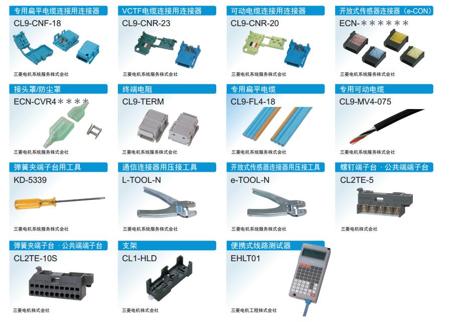
>> CL9-CNR-23 | MITSUBISHI Connector for VCTF cable connection CL9-CNR-23
CL9-CNR-23 | MITSUBISHI Connector for VCTF cable connection CL9-CNR-23
MITSUBISHI CL9-CNR-23 Manual And Instructions
CL9-CNR-23 datasheetPDF datasheet
MITSUBISHI CL9-CNR-23 Product information and technical parameters:
Brand: MITSUBISHI
Name: Connector for VCTF cable connection
Model: CL9-CNR-23
No introduction
...More relevant models >>>>
CL9-CNR-23 datasheetPDF datasheet
MITSUBISHI CL9-CNR-23 Product information and technical parameters:
Brand: MITSUBISHI
Name: Connector for VCTF cable connection
Model: CL9-CNR-23
No introduction
No introductionInput type: DC input, positive common end.
Input points: 16 points.
Enter the response time: 1.5ms the following.
Rated input voltage / current: DC24V/7mA.
External connection: 2~4 line type.
Waterproof connector type.
Strong waterproof type of IP67 protection grade.
No need to stop the system can be replaced module MITSUBISHI CL9-CNR-23.
Without the use of tools can be a simple connection, save time CL9-CNR-23
Terminal resistor built-in.
Can be installed along the 6 direction.
Hardware simulation method is to use a number of hardware equipment to simulate the generation of the signal,
The signals are connected to the input end of the PLC system in a hard wired way, and the timeliness is strong.
Software simulation method is in the MITSUBISHI PLC in the preparation of a set of simulation program,
The simulation provides the field signal, which is simple and easy to operate, but it is not easy to guarantee the timeliness MITSUBISHI CL9-CNR-23.
Simulation of the process of debugging, debugging method can be used to segment, and the monitoring function of programmer. Screw, 2 piece type terminal
Temperature measuring resistor body input module MITSUBISHI CL9-CNR-23.
Number of channels: 4 channels.
Number of stations: 1 stops.
Station type: remote equipment station.
MITSUBISHI PLC online debugging.
On-line debugging is the process that will through the simulation debugging to further carry on the on-line unification to adjust.
On-line debugging process should be step by step,
From MITSUBISHI PLC only connected to the input device, and then connect the output device, and then connect to the actual load and so on and so on step by step.
If you do not meet the requirements, the hardware and procedures for adjustment.
Usually only need to modify the part of the program can be.
MITSUBISHI PLC hardware implementation
Hardware implementation is mainly for the control cabinet and other hardware design and field construction.
Design control cabinet and the operating table and other parts of tthe electrical wiring diagram and wiring diagram CL9-CNR-23.
Electrical interconnection diagram of each part of the design system.
According to the construction drawings of the site wiring, and carry out a detailed inspection.
Because the program deesign and hardware implementation can be carried out at the same time,
So the design cycle of the MITSUBISHI PLC control system can be greatly reduced CL9-CNR-23.
...More relevant models >>>>
 Last one: MITSUBISHI Connector for connection of special flat cable CL9-CNF-18
 next one: MITSUBISHI Connector for connecting movable cable CL9-CNR-20
Related download