
Home
>> Products
>> MITSUBISHI
>> Ans/QnAs series PLC
>> Positioning control module
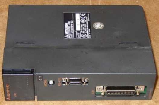
>> A1SD75P1-S3 | MITSUBISHI Positioning control module A1SD75P1-S3
A1SD75P1-S3 | MITSUBISHI Positioning control module A1SD75P1-S3
MITSUBISHI A1SD75P1-S3 Manual And Instructions
A1SD75P1-S3 datasheetPDF datasheet
A1SD75P1-S3 HardwareUser's Manual
A1SD75P1-S3 User's Manual
A1SD75P1-S3 HardwareUser's Manual
MITSUBISHI A1SD75P1-S3 Product information and technical parameters:
Brand: MITSUBISHI
Name: Positioning control module
Model: A1SD75P1-S3
Axis of control: 1.
A1SD75 series components show the MITSUBISHI in the manufacture and design of CNC, frequency converter,
Integrated technical experience in servo system and PLC.
These components have a wealth of features that are sufficient to meet the highest requirements in the application of positioning control.
Up to 3 axis linkage operation,
In low cost motion control applications, this component can be used to control the operation of a multi - to 3 axis, which can be used to account for only one slot.
...More relevant models >>>>
A1SD75P1-S3 datasheetPDF datasheet
A1SD75P1-S3 HardwareUser's Manual
A1SD75P1-S3 User's Manual
A1SD75P1-S3 HardwareUser's Manual
MITSUBISHI A1SD75P1-S3 Product information and technical parameters:
Brand: MITSUBISHI
Name: Positioning control module
Model: A1SD75P1-S3
Axis of control: 1.
A1SD75 series components show the MITSUBISHI in the manufacture and design of CNC, frequency converter,
Integrated technical experience in servo system and PLC.
These components have a wealth of features that are sufficient to meet the highest requirements in the application of positioning control.
Up to 3 axis linkage operation,
In low cost motion control applications, this component can be used to control the operation of a multi - to 3 axis, which can be used to account for only one slot.
Type of input: DC leakage.
Input points: 8 points.
Input voltage: DC24.
Input current: 7mA.
Output type: transistor drain type.
Output points: 8 points.
Common public end points: 8.
PLC is introduced by the relay control technology after the development of micro processing technology,
Can be easily and reliably used for switching control MITSUBISHI A1SD75P1-S3.
As the analog quantity can be converted into digital quantity, the number of digital quantity is just a number of switching value,
Therefore, after the conversion of analog, PLC can also be reliable for processing control A1SD75P1-S3
Because the continuous production process often has the analog quantity, the analog quantity control is sometimes called process control MITSUBISHI A1SD75P1-S3.
Analog quantity is not electricity, and PLC can only handle digital quantity, quantity of electricity.
All to realize the conversion between them to have the sensor, the analog quantity into a number of power.
If this power is not standard, but also through the transmitter,
The non-standard power into a standard electrical signal, such as 1-5V, 4-20mA, 0-10V, etc..
At the same time, there is also an analog input unit (A/D),
Transform these standard electrical signals into digital signals,
The analog output unit (D/A), in order to transform the digital quantity after PLC processing into analog quantity -- standard electric signal MITSUBISHI A1SD75P1-S3.
So the standard telecommunication number, the conversion between the number of operations to use a variety of computing.
This requires the resolution of the analog unit and the standard electrical signal. Number of channels: 2 channels.
Input signal: RS422A EIA.
Counter: 10KPPS/1 with the highest frequency.
A1SD62, A1SD62D and A1SD62E are 2 channel high speed counter components for AnS series PLC.
They are improved in comparison with A1SD61 in the following ways: the density of channels.
In order to require a higher resolution and operating speed of the application to provide a higher count rate, reduce costs.
The instruction list programming language is a programming language similar to assembly language mnemonic,
As well as assembly language by the operation code and the number of operations.
In the case of the computer for the PLC handheld programmer compile user program.
At the same time, the programming language of the instruction list corresponds to the ladder diagram programming language,
In PLC programming software can be converted to each other. Figure 3 is the instruction sheet corresponding to the ladder diagram of figure 2PLC.
The characteristics of instruction table programming language is used to represent mnemonic operation function,
Easy to remember, easy to grasp;
In the handheld programmer on the keyboard using the mnemonic representation, easy to operate, can be programmed in computer;
There is a one-to-one correspondence between the ladder diagram and the ladder diagram. Its characteristics are basically consistent with the ladder diagram language.
Functional block diagram language is a kind of PLC programming language, which is similar to digital logic circuit.
The function module is used to represent the function of the module,
Different function modules have different functions.
Functional module figure programming language features: functional block diagram programming language is characterized by a functional module for the unit,
Analysis and understanding of the control scheme is simple and easy: function module is to use graphical form of expression,
Intuitive, for a digital logic circuit based on the design of the staff is very easy to master the programming;
Control system with complex scale and complex control logic,
Because the function module diagram can clearly express the function relation, the programming debugging time is greatly reduced.
The popularization and application of PLC programming has been developed rapidly in our country,
It has been widely used in all kinds of mechanical equipment and production process of electrical control devices,
All walks of life have emerged a large number of application of PLC transformation of the results of the equipment.
Understand the working principle of PLC, have the ability to design, debug and maintain the PLC control system,
Has become the basic requirements of modern industry for electrical technicians and engineering students.
PLC user program is designned according to the control system of the process control requirements,
PLC programming language through the preparation of specifications, in accordance with the actual needs of the use of the function to design A1SD75P1-S3.
As long as the user caan master some kind of standard programming language,
To be able to use PLC in the control system,
To achieve a variety of automatic control functions A1SD75P1-S3.
...More relevant models >>>>
 Last one: MITSUBISHI Positioning module A1SD75P3
 next one: MITSUBISHI Positioning control module A1SD75P2-S3
Related download