
Home
>> Products
>> MITSUBISHI
>> Ans/QnAs series PLC
>> Other function modules
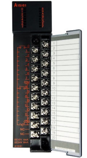
>> A1SI61 | MITSUBISHI High speed interrupt module A1SI61
A1SI61 | MITSUBISHI High speed interrupt module A1SI61
MITSUBISHI A1SI61 Manual And Instructions
A1SI61 datasheetPDF datasheet
A1SI61 HardwareUser's Manual
MITSUBISHI A1SI61 Product information and technical parameters:
Brand: MITSUBISHI
Name: High speed interrupt module
Model: A1SI61
A1SI61 is designed to control the application of mechanical devices that require high speed response time.
A1SI61 temporarily stop running in order to generate an interrupt signal when the program is running,
And according to the interrupt vector to execute the corresponding interrupt handler.
The interrupt start condition can be selected according to the type of the connected device,
That is, the rising edge of the interrupt signal can be selected as a starting signal, and the falling edge of the interrupt signal can be selected as an interrupt.
The popularization and application of PLC programming has been developed rapidly in our country,
It has been widely used in all kinds of mechanical equipment and production process of electrical control devices,
All walks of life have emerged a large number of application of PLC transformation of the results of the equipment.
Understand the working principle of PLC, have the ability to design, debug and maintain the PLC control system,
Has become the basic requirements of modern industry for electrical technicians and engineering students.
The instruction list programming language is a programming language similar to assembly language mnemonic,
As well as assembly language by the operation code and the number of operations.
In the case of the computer for the PLC handheld programmer compile user program.
At the same time, the programming language of the instruction list corresponds to the ladder diagram programming language,
In PLC programming software can be converted to each other. Figure 3 is the instruction sheet corresponding to the ladder diagram of figure 2PLC.
The characteristics of instruction table programming language is used to represent mnemonic operation function,
Easy to remember, easy to grasp;
In the handheld programmer on the keyboard using the mnemonic representation, easy to operate, can be programmed in computer;
There is a one-to-one correspondence between the ladder diagram and the ladder diagram. Its characteristics are basically consistent with the ladder diagram language.
...More relevant models >>>>
A1SI61 datasheetPDF datasheet
A1SI61 HardwareUser's Manual
MITSUBISHI A1SI61 Product information and technical parameters:
Brand: MITSUBISHI
Name: High speed interrupt module
Model: A1SI61
A1SI61 is designed to control the application of mechanical devices that require high speed response time.
A1SI61 temporarily stop running in order to generate an interrupt signal when the program is running,
And according to the interrupt vector to execute the corresponding interrupt handler.
The interrupt start condition can be selected according to the type of the connected device,
That is, the rising edge of the interrupt signal can be selected as a starting signal, and the falling edge of the interrupt signal can be selected as an interrupt.
The popularization and application of PLC programming has been developed rapidly in our country,
It has been widely used in all kinds of mechanical equipment and production process of electrical control devices,
All walks of life have emerged a large number of application of PLC transformation of the results of the equipment.
Understand the working principle of PLC, have the ability to design, debug and maintain the PLC control system,
Has become the basic requirements of modern industry for electrical technicians and engineering students.
The instruction list programming language is a programming language similar to assembly language mnemonic,
As well as assembly language by the operation code and the number of operations.
In the case of the computer for the PLC handheld programmer compile user program.
At the same time, the programming language of the instruction list corresponds to the ladder diagram programming language,
In PLC programming software can be converted to each other. Figure 3 is the instruction sheet corresponding to the ladder diagram of figure 2PLC.
The characteristics of instruction table programming language is used to represent mnemonic operation function,
Easy to remember, easy to grasp;
In the handheld programmer on the keyboard using the mnemonic representation, easy to operate, can be programmed in computer;
There is a one-to-one correspondence between the ladder diagram and the ladder diagram. Its characteristics are basically consistent with the ladder diagram language.
The most appropriate temperature regulation control (PID control) is possible,
In order to control the PID does not need to specify a special command.
In addition, according to the automatic regulation function,
The automatic setting of PID number is possible.
The length of time required to execute the instruction, the length of the user''s program, the type of instruction, and the speed of the CPU execution are very significant,
Generally, a scanning process, the fault diagnosis time,
Communication time, input sampling and output refresh time is less,
The execution time is accounted for the vast majority of MITSUBISHI A1SI61 A1SI61
The response time of PLC is the interval between the time of the change of the external output signal of the PLC and the time of the change of the external output signal which is controlled by it,
Lag time, this is the time constant of the input circuit,
The time constant of the output circuit, the arrangement of the user statement and the use of the instruction,
The cycle scan mode of PLC and the way of PLC to refresh the I/O and so on MITSUBISHI A1SI61.
This phenomenon is called the I/O delay time effect MITSUBISHI A1SI61. Output type: relay.
Output points: 16 points.
Load voltage: AC240/DC24.
Load current: 2A.
Connection mode: terminal row.
Common public end points: 8.
Sequential function flow chart language is designed to satisfy the sequential logic control.
The process of sequential process action is divided into steps and transformation conditions,
According to the transfer condition, the control system is distributed in the function flow sequence,
Step by step according to the sequence of actions.
Each step represents a control function, represented by the box.
In the box, the ladder logic is used to complete the task of the corresponding control function.
This programming language makes the program structure clear and easy to read and maintain,
Greatly reduce the programming workload, shorten the programming and debugging time.
Used in the system of the size of the school, procedures for more complex occasions.
Sequence function flow chart programming language features: to function as the main line, in accordance with the functtional flow of the order of distribution, clear, easy to understand the user program,
Avoid the defect of ladder diagram or other languages,
At the same time, the use of ladder language to avoid the use of ladder programming,
Due to the compllicated mechanical interlock, the structure of the user program is complex and difficult to understand,
User program scan time is also greatly reduced A1SI61 A1SI61.
...More relevant models >>>>
 Last one: MITSUBISHI Master control module A1SJ71T32-S3
 next one: MITSUBISHI I/O bus monitoring module A1SS91
Related download