
Home
>> Products
>> MITSUBISHI
>> A/QnA series PLC
>> CPU
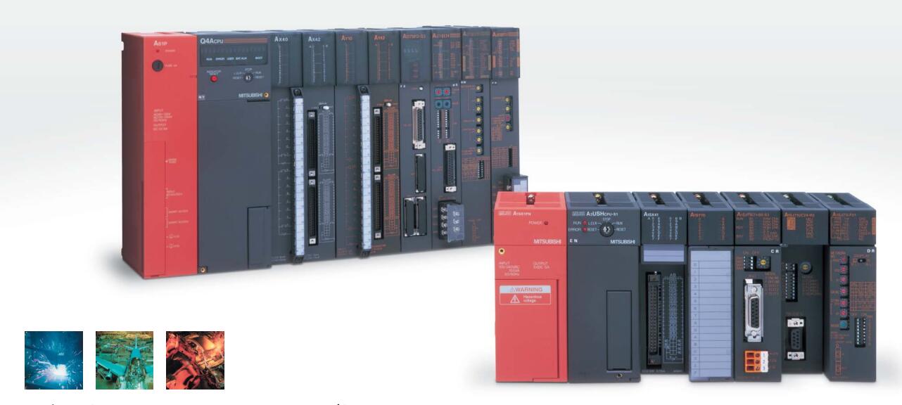
>> A73CPUP21-S3 | MITSUBISHI Moving CPU unit A73CPUP21-S3
A73CPUP21-S3 | MITSUBISHI Moving CPU unit A73CPUP21-S3
MITSUBISHI A73CPUP21-S3 Manual And Instructions
A73CPUP21-S3 Common InstructionsProgramming Manual
A73CPUP21-S3 Dedicated InstructionsProgramming Manual
A73CPUP21-S3 FundamentalsProgramming Manual
MITSUBISHI A73CPUP21-S3 Product information and technical parameters:
Brand: MITSUBISHI
Name: Moving CPU unit
Model: A73CPUP21-S3
Special multi axis positioning controller for NSD servo system.
Optical data communication line.
Program capacity: Max 60K step.
Input / output points: 1920 points.
When the switch is off, the diode does not emit light, and the transistor is not on the way. Internal circuit input signal.
It is through the input interface circuit to the external switch signal into PLC internal can accept the digital signal.
Photoelectric three levels: in the light of the light signal conduction, the degree of light signal and the intensity of the light signal.
The output signal has a linear relationship with the input signal in the linear operating region of the photoelectric coupler.
User program storage capacity: it is a measure of how much the user application can store the number of indicators.
Usually in words or K words as units. 16 bit binary number is a word,
Every 1024 words are 1K words. PLC to store instructions and data in words.
General logical operation instructions each account for 1 words. Timer / counter,
Shift instruction accounted for 2 words. Data operation instructions for 2~4.
The length of time required to execute the instruction, the length of the user''s program, the type of instruction, and the speed of the CPU execution are very significant,
Generally, a scanning process, the fault diagnosis time,
Communication time, input sampling and output refresh time is less,
The execution time is accounted for the vast majority of.
The photoelectric coupler is composed of two luminous two extreme tubes and a photoelectric transistor.
Light emitting diode two: the input of a photo coupler and the change of electrical signal,
The light signal is generated by the light emitting diode, which is the same as the input signal.
The working process of the input interface circuit: when the switch is closed, the diode light,
The transistor is then guided to the internal circuit and input signal under the irradiation of the light.
...More relevant models >>>>
A73CPUP21-S3 Common InstructionsProgramming Manual
A73CPUP21-S3 Dedicated InstructionsProgramming Manual
A73CPUP21-S3 FundamentalsProgramming Manual
MITSUBISHI A73CPUP21-S3 Product information and technical parameters:
Brand: MITSUBISHI
Name: Moving CPU unit
Model: A73CPUP21-S3
Special multi axis positioning controller for NSD servo system.
Optical data communication line.
Program capacity: Max 60K step.
Input / output points: 1920 points.
When the switch is off, the diode does not emit light, and the transistor is not on the way. Internal circuit input signal.
It is through the input interface circuit to the external switch signal into PLC internal can accept the digital signal.
Photoelectric three levels: in the light of the light signal conduction, the degree of light signal and the intensity of the light signal.
The output signal has a linear relationship with the input signal in the linear operating region of the photoelectric coupler.
User program storage capacity: it is a measure of how much the user application can store the number of indicators.
Usually in words or K words as units. 16 bit binary number is a word,
Every 1024 words are 1K words. PLC to store instructions and data in words.
General logical operation instructions each account for 1 words. Timer / counter,
Shift instruction accounted for 2 words. Data operation instructions for 2~4.
The length of time required to execute the instruction, the length of the user''s program, the type of instruction, and the speed of the CPU execution are very significant,
Generally, a scanning process, the fault diagnosis time,
Communication time, input sampling and output refresh time is less,
The execution time is accounted for the vast majority of.
The photoelectric coupler is composed of two luminous two extreme tubes and a photoelectric transistor.
Light emitting diode two: the input of a photo coupler and the change of electrical signal,
The light signal is generated by the light emitting diode, which is the same as the input signal.
The working process of the input interface circuit: when the switch is closed, the diode light,
The transistor is then guided to the internal circuit and input signal under the irradiation of the light.
Extension cable.
Length: 2000mm. Output points: 64 points.
Voltage: DC12/24V.
OFF leakage current: 0.1mA.
Output type: transistor output (type sink).
Response time: 0.3ms.
32 points / a common end.
40 pin connector.
With the surge absorber.
High speed output type.
Each scanning process. Focus on the input signal sampling MITSUBISHI A73CPUP21-S3. Focus on the output signal to refresh.
Input refresh process A73CPUP21-S3 When the input port is closed,
Program in the implementation phase, the input end of a new state, the new state can not be read.
Only when the program is scanned, the new state is read.
A scan cycle is divided into the input sample, the program execution, the output refresh.
The contents of the component image register are changed with the change of the execution of the program MITSUBISHI A73CPUP21-S3.
The length of the scan cycle is determined by the three.
CPU the speed of executing instructions.
Time of instruction.
Instruction count.
Due to the adoption of centralized sampling.
Centralized output mode.
There exist input / output hysteresis phenomena, i.e., the input / output response delay.
PLC selection with the development of PLC technology, more and more types of PLC products,
Function is becoming more and more perfect, and its application is more and more extensive MITSUBISHI A73CPUP21-S3.
Different series of different models of PLC has different performance, applicable occasions also have different emphasis,
Price also has a greater difference. Therefore PLC selection,
Under the premise of meeting the control requirements,
Should consider the best performance to price ratio, a reasonable choice of PLC.
System program memory for storing system program,
Including management procedures, monitoring procedures, as well as the user program to do the compiler to compile the process of interpretation.
Read only memory. Manufacturers use, content can not be changed, power does not disappear. SI/QSI/H-PCF/ wide range H-PCF fiber optic cable.
Double loop.
Remote I/O network (remote control station).
How to choose MITSUBISHI PLC.
MITSUBISHI PLC options include the choice of MITSUBISHI PLC models, capacity, I/O module, power, etc..
MITSUBISHI PLC distribution I/O points and design MITSUBISHI PLC peripheral hardware circuit
Draw the I/O point of the PLC and the input / output device connection diagram or the corresponding table,
This part also can be carried out in second steps.
Design PLC peripheral hardware circuit A73CPUP21-S3.
Draw the electrical wiring diagram of the other parts of the system,
Including the main circuit and the control circuit does not enter the PLC, etc..
The electrical schematic diagram of the system compoosed of I/O PLC connection diagram and PLC peripheral electrical circuit diagram A73CPUP21-S3.
So far the system''s hardware electrical circuit has been determined.
...More relevant models >>>>
 Last one:
  next one:
 Related download